
close
Choose Your Site
Global
Social Media


Views: 0 Author: Site Editor Publish Time: 2026-07-16 Origin: Site


Transitioning pipe diameters in aggressive fluid or high-purity systems introduces a critical vulnerability point. Choosing the wrong adapter material creates immediate risks. These risks include catastrophic leaks, cross-contamination, or systemic pressure failures. Metallic or standard plastic reducers often work fine for basic utilities. However, highly corrosive or ultra-pure applications require specialized engineering solutions. You must use materials designed for extreme chemical environments. This guide provides a technical decision framework for specifying a PTFE reducing connector. We outline exact use cases where these components excel. You will also learn about their performance limitations and implementation risks. By understanding these factors, you can protect your fluid transfer systems from unexpected downtime. You will discover exactly when and how to deploy these critical adapters safely.
PTFE reducers are mandatory when transitioning line sizes in systems handling highly reactive chemicals or requiring ultra-pure (zero-leach out) conditions.
While they offer unmatched chemical inertness (pH 0-14), they are susceptible to "cold flow" (creep) and must be de-rated for high-pressure/high-temperature applications.
Proper installation is connection-dependent; a common industry point of failure is improperly applying PTFE tape to compression-style fluoropolymer reducers.
Specifying the correct corrosion-resistant reducer requires aligning mechanical load, media compatibility, and system temperature thresholds.
Reducing line sizes naturally increases fluid velocity and turbulence. This dynamic change accelerates physical wear inside the piping system. It also amplifies chemical attack on the reducer component itself. Standard materials simply cannot withstand this localized stress in harsh environments.
You will see rapid chemical degradation when using stainless steel, PVC, or standard nylon adapters. These materials fail quickly when exposed to halogens or aggressive solvents. They also dissolve under strong acids like hydrofluoric acid. The resulting structural damage leads to dangerous environmental leaks.
Beyond physical leaks, you face severe contamination risks. Semiconductor manufacturing and pharmaceutical processing demand absolute purity. Standard adapters release metal ions or plasticizer gases into the fluid path. This microscopic off-gassing can destroy entire product batches. Such losses cost facilities significantly in wasted materials.
These failure modes trigger a clear engineering solution. A fluoropolymer reducer becomes necessary under specific conditions. You need one when your system demands complete chemical inertness. It is also required when you need zero contamination and a frictionless flow transition. Transitioning to this material eliminates the vulnerabilities of standard plastics and metals.
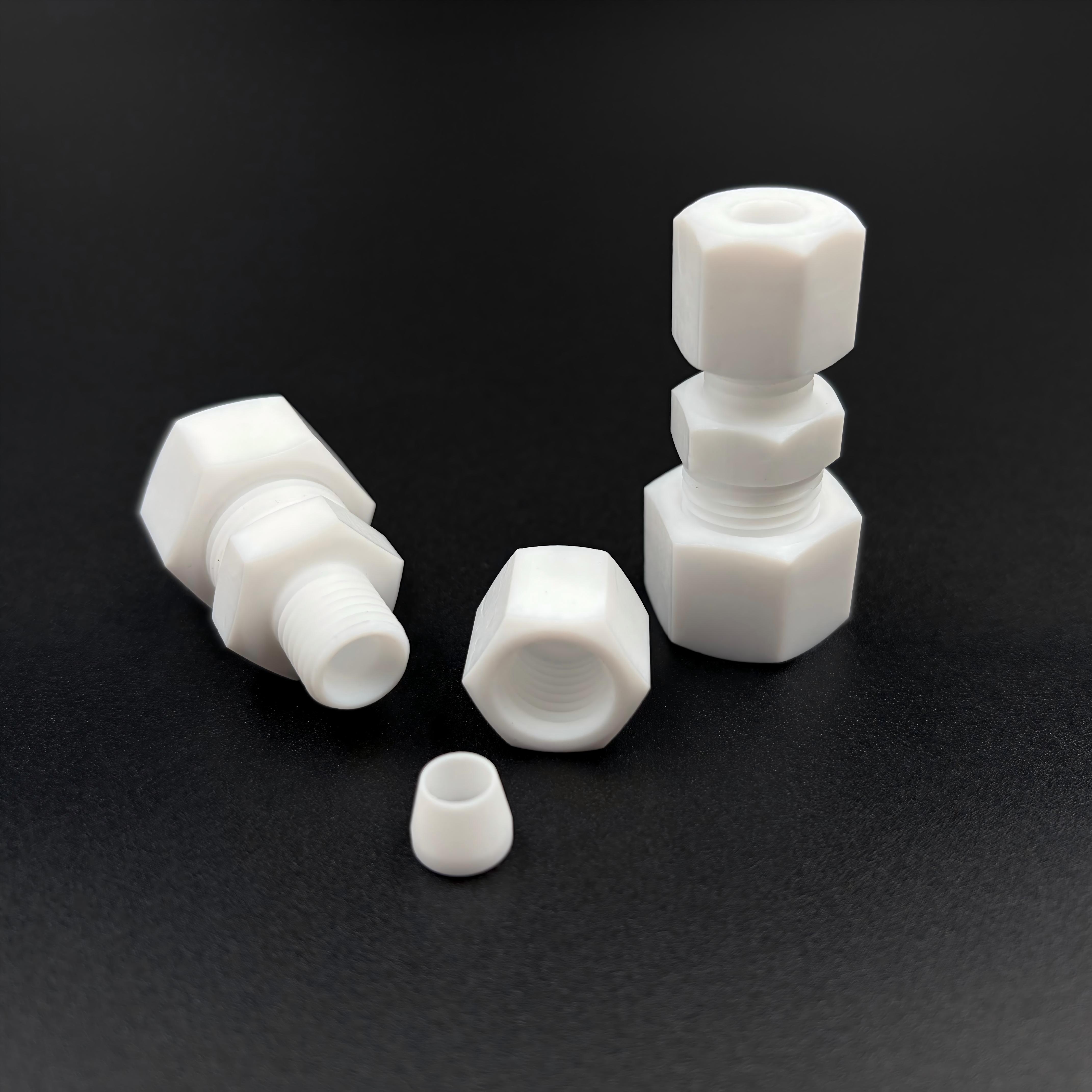
Engineers must evaluate media compatibility first. Absolute chemical inertness makes PTFE unique. It handles practically all industrial chemicals without degrading. This universal compatibility makes it the default chemical line connector for mixed-media manifolds. You do not need to stock different materials for different acid lines.
You must also assess the thermal operational range. PTFE maintains structural stability across extreme temperature variations. It functions reliably from -328°F to 500°F (-200°C to 260°C). This broad range supports both cryogenic transfers and high-heat sterilization cycles.
Surface friction directly impacts FDA and USP compliance requirements. Analyze your flow requirements carefully. PTFE features an ultra-low coefficient of friction. This slick surface prevents media buildup and scaling in the reduction zone. It also prevents bacterial adhesion, which ensures sanitary processing conditions.
Consider the dielectric strength of your operating environment. Mixed-material pipelines often suffer from galvanic corrosion. PTFE serves as a highly effective electrical insulator. It breaks the electrical conductivity path between dissimilar metals. This characteristic extends the lifespan of adjacent metallic piping.
Material Option | Chemical Resistance | Maximum Temperature | Purity Risk Profile |
|---|---|---|---|
Virgin PTFE | Excellent (pH 0-14) | 500°F (260°C) | Zero Leaching |
Stainless Steel (316L) | Moderate (Fails in Halogens) | >1000°F (537°C) | Metal Ion Leaching |
Standard PVC | Poor in Solvents | 140°F (60°C) | Plasticizer Off-gassing |
You must understand the reality of "cold flow" or creep. PTFE deforms over time under continuous mechanical stress. High internal pressure accelerates this structural distortion. You must frame the necessity for reinforced PTFE if mechanical loads are high. Manufacturers often use glass or carbon fillers to improve dimensional stability.
Engineers must calculate pressure-temperature de-rating curves. Maximum pressure ratings drop significantly as system temperatures increase. A fitting rated for 150 PSI at room temperature may only handle 50 PSI at 300°F. Virgin PTFE is not suitable for simultaneous high-pressure and high-heat combinations. You need external metallic reinforcement for those extremes.
Abrasive media handling presents another serious limitation. Virgin PTFE offers poor wear resistance against highly abrasive slurries. Sand, metallic shards, or crystalline fluids will score the inner walls quickly. This erosion compromises the wall thickness and leads to premature rupture.
Knowing when to pivot to alternative solutions is crucial for safety. Keep these guidelines in mind:
Choose PFA when you need visual flow clarity or higher flex life.
Select Hastelloy or Titanium for systems combining extreme pressure with extreme corrosion.
Use glass-filled PTFE when you need chemical resistance but face heavy compressive loads.
Opt for metal-clad fluoropolymer fittings in volatile, high-vibration environments.
Choosing the proper mechanical interface prevents system leaks. You must break down the specific mechanics of your PTFE pipe adapter. Each connection style serves a distinct operational purpose.
Threaded (NPT): Best for standard low-pressure industrial piping. They are easy to install but vulnerable to over-tightening.
Compression: Best for high-purity tubing systems. They allow frequent disassembly without destroying the seal.
Flare: Optimal for minimizing dead volume. They ensure smooth, high-purity flow transitions in semiconductor lines.
The PTFE tape controversy causes frequent installation failures. Field plumbing data highlights a common installer error. Mechanics routinely apply sealant tape out of habit. We must explicitly clarify that PTFE tape should only be used on NPT threads. Using tape on PTFE compression fittings disrupts the ferrule's mechanical seal. This mistake induces immediate, hard-to-trace leaks.
Torque specifications require strict adherence during assembly. Plastic threads behave differently than brass or steel. Highlight the risk of over-tightening PTFE threads to your maintenance team. Excessive force causes thread shearing instantly. It also triggers immediate cold flow distortion, permanently ruining the adapter.
You must determine the step-down ratio precisely. Match the Outer Diameter (OD) and Inner Diameter (ID) requirements perfectly. Incorrect sizing creates flow bottlenecks or dead legs. For example, stepping down from 1/2" to 1/4" NPT requires specific wall thicknesses. This prevents turbulence from degrading the transition point.
Engineers should always validate material certifications before procurement. Ensure the vendor provides accurate material test reports (MTRs). These documents confirm the use of virgin PTFE versus reprocessed PTFE. Reprocessed materials compromise structural integrity and introduce microscopic impurities. High-purity applications strictly forbid reprocessed fluoropolymers.
System integration mapping ensures long-term compatibility. Verify how the reducer connects with existing piping architecture. Transitioning from a flexible PFA tube to a rigid PTFE NPT block requires specific ferrule designs. Map these connection points to avoid mismatched thread pitches or incompatible seal angles.
Finally, conduct a practical lifespan analysis. Justify the higher initial procurement cost of a proper corrosion-resistant reducer. Premium fluoropolymers drastically reduce maintenance downtime. They also extend system replacement cycles. Paying more upfront eliminates the recurring labor costs of replacing degraded standard plastic fittings.
A PTFE reducing connector serves as a highly specialized fluid management component. It is engineered specifically to solve severe chemical and purity challenges. You deploy it exactly where traditional metals and standard plastics fail. Recognizing its unique capabilities protects your infrastructure.
You should base your final purchasing decision on strict engineering metrics. Always perform precise pressure-temperature matching before installation. Verify you have selected the correct connection styling, distinguishing between threads and compression fittings. This diligence prevents catastrophic leaks.
Your next step requires active verification. Direct your procurement team to review specific dimensional tolerance tables. Download technical CAD files to model the integration virtually. Consult an applications engineer to verify full system compatibility before finalizing your order.
A: No. Virgin PTFE is prone to cold flow and deformation under high mechanical pressure. High-pressure hydraulic lines require reinforced materials or metal-clad fluoropolymer fittings to prevent sudden bursts and maintain structural integrity.
A: Generally, yes for NPT threads to ensure a proper seal. However, it requires much less torque and tape than metal fittings. Using too much tape or force will crack the female thread.
A: Both are robust fluoropolymers. PTFE is generally opaque, slightly more cost-effective, and machined from solid blocks. PFA is translucent, allowing visible flow. It is injection-molded and offers slightly better flex life and creep resistance.
A: Yes, PTFE features excellent thermal shock resistance. However, the mechanical connections, especially threaded joints, must be monitored. Thermal expansion and contraction cycles can cause these connections to loosen over time.


