
close
Choose Your Site
Global
Social Media


Views: 0 Author: Site Editor Publish Time: 2026-08-03 Origin: Site


Sizing components for aggressive fluid handling requires moving beyond basic internal diameter measurements. Relying on simple pipe charts often triggers disastrous systemic failures. Incorrectly sized fittings in chemical lines lead to flow bottlenecks. They also cause localized pressure spikes and premature mechanical failure. These physical problems escalate rapidly under elevated operating temperatures.
A single compromised joint threatens facility safety. It also forces unexpected operational downtime. Precise sizing prevents leaks and maximizes fluid handling efficiency. You must understand how chemical aggressiveness alters material behavior over time.
Our goal is to provide procurement teams and process engineers a predictable, standards-driven framework. You will learn to specify exact dimensions, pressure ratings, and tolerances. We will guide you through complex variables like thermal derating and jointing methods. By applying this specific methodology, you will design and maintain safe, compliant chemical processing networks.
Process engineers face strict baseline constraints when designing fluid networks. You cannot select a PPH pipe fitting based solely on thread size or arbitrary connection points. Chemical systems demand a rigid evaluation of fluid dynamics, temperature variations, and structural joining requirements.
Selecting the correct internal diameter (ID) prevents excessive friction. High friction causes severe head loss across your piping system. If your ID is too small, fluid velocity spikes. High velocity accelerates mechanical wear on the interior walls. Conversely, if your ID is too large, velocity drops. Slow-moving fluids allow suspended particles to settle. This settling creates dangerous sludge blockages in the line.
Chemical slurries require vastly different velocity calculations than pure water. Highly viscous acids resist flow naturally. You must calculate the Reynolds number for your specific chemical compound. This calculation ensures the chosen fitting ID maintains a steady, turbulent-free flow rate.
Pressure capacity decreases predictably as operating temperature increases. This represents a fundamental reality in thermoplastic engineering. A component sized purely for ambient pressure will fail in a high-temperature chemical process. Manufacturers establish nominal pressure ratings at a baseline of 20°C. Once your process fluid exceeds this baseline, the structural integrity of the polymer softens. You must account for this inverse dynamic early in the design phase.
The method you use to fuse the network directly dictates your dimensional focus. Engineers typically choose between two primary thermal fusion techniques. Each technique demands a different sizing approach.
Common Mistake: Procurement teams often order socket fusion components when the field contractors plan to use butt welding equipment. This mismatch halts installation immediately.
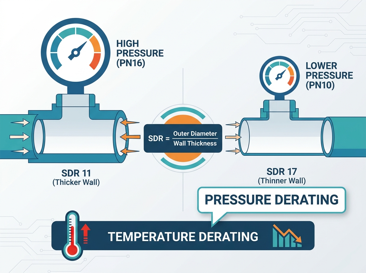
Understanding technical specifications prevents catastrophic blowouts. You must decode the alphanumerical ratings stamped on every thermoplastic component. These ratings dictate exactly how much stress the network can safely handle.
SDR defines the geometric relationship between the outer diameter and the wall thickness. We calculate it by dividing the pipe OD by its minimum wall thickness. This ratio confuses many junior engineers. You must remember a critical rule: lower SDR numbers mean thicker walls.
Thicker walls provide higher pressure ratings. For example, an SDR11 component possesses a thicker wall than an SDR17 component of the same outer diameter. When handling volatile chemical transfers, we generally recommend lower SDR values to guarantee maximum burst resistance.
European standards classify thermoplastics using Pressure Nominal (PN) classes. These classes represent the maximum allowable operating pressure in bars at 20°C. Common classes include PN10 (10 bar) and PN16 (16 bar). You must align your required PPH pipe fitting specifications with your system's peak operating pressure.
Surges happen frequently in industrial environments. Valve closures create rapid water hammer effects. If your baseline process runs at 8 bar, selecting a PN10 component leaves very little safety margin. Upgrading to a PN16 class protects the network against sudden pressure spikes.
Standard Dimension Ratio (SDR) and Nominal Pressure (PN) Equivalents at 20°C
| Standard Dimension Ratio (SDR) | Nominal Pressure Class (PN) | Maximum Allowable Pressure (Bar) | Typical Industrial Application |
|---|---|---|---|
| SDR 17.6 | PN 6 | 6 Bar | Gravity drains, low-pressure venting |
| SDR 17 | PN 10 | 10 Bar | Standard fluid transfer, cooling lines |
| SDR 11 | PN 16 | 16 Bar | Aggressive chemical dosing, high-pressure lines |
Always demand components manufactured to strict international standards. DIN 8077/8078 dictates the acceptable manufacturing dimensions and tolerances for polypropylene materials. ISO 15494 specifically governs plastic piping systems used for industrial applications.
These standards ensure uniform geometry. If you source materials non-compliant with DIN 8077/8078, you risk ovality defects. Roundness is mandatory for secure thermal welds. Relying on ISO 15494 ensures the polymer blend resists chemical degradation over its intended lifespan.
Ambient pressure ratings tell only half the story. Industrial chemical lines rarely operate at a comfortable 20°C. Active reactions generate significant heat. You must implement thermal derating protocols to ensure systemic safety.
Thermal derating adjusts the manufacturer's pressure rating downward based on operating heat. We apply specific derating factors to calculate the adjusted Maximum Allowable Operating Pressure (MAOP). If a process runs continuously at 80°C, a PN16 rated component will absolutely not support 16 bar of pressure.
Engineers calculate MAOP by multiplying the nominal pressure by the temperature derating factor. For example, if the derating factor at 80°C is 0.4, your PN16 component now safely handles only 6.4 bar (16 x 0.4). Integrating a chemical processing PPH pipe fitting requires mandatory review of these thermal curves.
Derating Factors for Polypropylene Homopolymer Systems
| Operating Temperature (°C) | Derating Factor Multiplier | Adjusted MAOP for PN16 (Bar) |
|---|---|---|
| 20°C | 1.00 | 16.0 Bar |
| 40°C | 0.85 | 13.6 Bar |
| 60°C | 0.65 | 10.4 Bar |
| 80°C | 0.40 | 6.4 Bar |
| 90°C | 0.25 | 4.0 Bar |
Heat weakens the polymer structure mechanically. Aggressive chemicals attack it chemically. Specific compounds, like high-concentration sulfuric acid or sodium hydroxide, accelerate polymer degradation. You cannot rely on thermal derating alone for these fluids.
Highly corrosive environments require additional safety margins. We recommend specifying thicker wall dimensions (lower SDR) than the pressure calculations initially suggest. This sacrificial wall thickness compensates for long-term internal surface erosion.
Sizing involves more than internal diameters and wall thickness. You must account for physical elongation. Thermoplastics expand significantly as temperatures rise. This phenomenon is known as linear thermal expansion.
If you fail to size the overall network length correctly, the pipe will snake or buckle between anchor points. You must integrate expansion loops or directional changes into your design. Properly sized components allow the pipeline to absorb thermal stress without cracking the fusion joints.
Standard off-the-shelf components handle most routing requirements. However, chemical facilities often feature complex, highly restrictive spatial environments. When standard inventory fails to meet your design criteria, custom fabrication becomes essential.
Standard 45-degree or 90-degree elbows consume significant physical space. They may not fit inside legacy infrastructure. Older plants feature dense piping corridors. Upgrading these systems requires navigating extremely tight footprints.
Complex skid-mounted dosing systems face similar challenges. Engineers build these skids to be as compact as possible. Standard tees and bulky flanges often clash with structural frames. A bespoke component solves these spatial clashes instantly.
Modernizing a facility means connecting new polymer networks to old metal infrastructure. You frequently encounter transitional sizing nightmares. You might need to join metric polymer lines to imperial stainless steel valves. Designing a custom PPH pipe fitting bridges these distinct material schedules perfectly.
Custom fabrications handle non-standard flanged equipment easily. They eliminate the need for clumsy, multi-part adapter trains. Single-piece custom transitions provide a cleaner, safer flow path.
Procurement teams must weigh the trade-offs of bespoke fabrication carefully. Custom orders impact project timelines.
Best Practice: Identify non-standard routing requirements during the initial 3D modeling phase. Order custom components immediately after finalizing the spatial model to mitigate lead time delays.
Engineering calculations hold no value if the physical product contains manufacturing defects. You must heavily scrutinize your manufacturing partners. A strict evaluation process prevents inferior materials from entering your facility.
A reliable PPH pipe fitting supplier must demonstrate strict control over geometric tolerances. Pay close attention to ovality and wall thickness consistency. Ovality refers to the deviation from a perfect circle.
If a component exhibits poor ovality, the welding machine cannot clamp it evenly. This deviation causes uneven heating. Uneven heating leads to weak welds and inevitable field failures. Ask suppliers for their standard dimensional tolerance data before issuing purchase orders.
The origin of the polymer blend dictates its chemical resistance. Ensure the supplier uses 100 percent virgin Polypropylene Homopolymer. Some budget manufacturers blend virgin resin with regrind (recycled plastic scrap).
Regrind compromises the molecular chain of the plastic. It creates unpredictable weak points within the wall structure. These weak points fail rapidly under aggressive chemical exposure. Demand material traceability certificates detailing the exact batch of virgin resin used.
Do not rely on marketing claims. Evaluate the supplier’s internal Quality Assurance (QA) processes rigorously. You should request specific batch-testing data.
Sizing thermoplastic components for aggressive chemical handling is a complex, multi-variable equation. You cannot rely on guesswork. Successful design requires balancing fluid flow rates, operating temperatures, SDR requirements, and chemical compatibility. Neglecting any single variable compromises the safety of your entire fluid network.
We recommend finalizing your piping and instrumentation diagram (P&ID) immediately. Once complete, calculate all thermal derating factors based on your peak expected operating temperatures. Map these calculations against standard SDR and PN classes.
Before issuing a Request for Quotation (RFQ), encourage your engineering teams to engage directly with manufacturers. Request comprehensive material specification sheets and proprietary thermal derating charts from your shortlisted manufacturers. Use this hard data to validate your sizing models and ensure a safe, long-lasting chemical process installation.
A: The primary difference lies in wall thickness and pressure capacity. SDR11 features a thicker wall and typically supports PN10 to PN16 pressures, depending on temperature. We use SDR11 for high-pressure or aggressive chemical lines. SDR17 is thinner, supporting PN6 to PN10 pressures. It serves best in lower-pressure, gravity-fed, or ventilation lines.
A: No. PPH typically follows metric DIN and ISO standards, measuring the outer diameter strictly in millimeters. PVC piping often utilizes IPS (Iron Pipe Size) or Schedule 40/80 dimensions, especially in North America. You cannot mix these sizing conventions without specialized adapter fittings.
A: Socket fusion requires the fitting to slip entirely over the pipe. This method focuses heavily on exact outer diameter (OD) tolerances. Butt welding requires the pipe and the fitting to meet end-to-end. This demands an identical SDR and wall thickness to ensure a flush, unobstructed internal fluid bore.


