
close
Choose Your Site
Global
Social Media


Views: 0 Author: Site Editor Publish Time: 2026-07-18 Origin: Site


Fluid handling systems rely heavily on precise connections to maintain optimal flow and pressure. System designers often face a crucial choice when routing these networks. Selecting the wrong fitting can lead to system inefficiencies, turbulence, and unexpected pressure drops. You must understand the specific flow requirements of your layout to prevent structural stress. Comparing reducing tee vs equal tee configurations helps you direct fluids accurately while preserving system stability. This decision matters deeply because it dictates the functional integrity of your entire piping infrastructure.
In this article, we will explore the fundamental differences between these two vital components. You will learn how to evaluate fluid dynamics, dimensional constraints, and spatial layout requirements. We will also cover material considerations and practical installation methods. These insights will guide your next project smoothly. You can then build robust networks capable of handling demanding industrial conditions.
Piping networks require strategic branching to distribute fluids effectively across different zones. Engineers use specialized components to split or combine these fluid streams. A standard three-way pipe fitting serves as the fundamental building block for these junctions. It features one inlet and two outlets, or two inlets and one outlet. This T-shaped geometry allows you to route liquids or gases exactly where they need to go. You will encounter two primary variations of this component in almost every industrial or commercial layout.
Equal configurations maintain uniform pipe diameters across all three connection points. The main run and the intersecting branch share the exact same internal dimensions. You use these components when you need to split a main supply line into two equal streams. They ensure consistent flow capacity across the entire junction. Installers frequently place them in header systems. They work perfectly when downstream equipment requires the same volume as the main supply line.
Reducing configurations alter the diameter of the intersecting branch. The main run maintains a consistent size, but the side outlet shrinks to a smaller dimension. You install these components to draw off a smaller portion of the main flow. They allow you to feed secondary equipment without starving the primary pipeline. This design eliminates the need for extra adapter bushings. It keeps your piping layout compact and clean. You save physical space while achieving precise volumetric control.
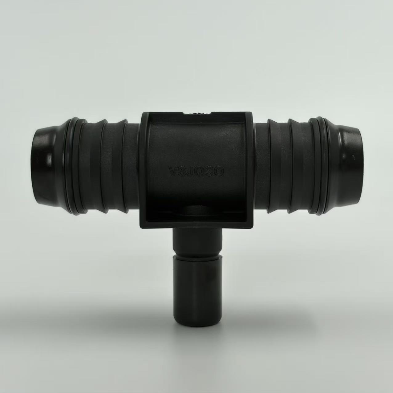
The physical geometry of a fitting dictates its behavior within a pressurized network. You must recognize these structural variations to plan your network accurately. Both designs share a basic T-shape. However, their internal dimensions create vastly different fluid behaviors. These geometric differences influence everything from system footprint to installation techniques. We can break down the primary structural differences into several key areas.
Port Dimensions: Equal types feature three identical ports. Reducing types feature two identical run ports and one smaller branch port.
Space Utilization: Reducing types condense the branching mechanism into a single unit. They require less physical clearance than an equal fitting paired with a separate size adapter.
Weight Distribution: Symmetrical components distribute mechanical stress evenly. Asymmetrical components concentrate varying levels of stress near the smaller branch transition.
Flow Resistance: Identical ports maintain consistent flow resistance. A smaller branch port introduces sudden resistance and alters local fluid velocity.
You must evaluate these structural traits against your physical space constraints. Tight equipment enclosures often demand compact branching solutions. You might lack the linear space required for bulky adapter combinations. In these scenarios, a purpose-built reducing component solves the spatial puzzle immediately. It streamlines the assembly process and reduces potential leak points. Every additional joint you add increases the risk of future system failure. Simplifying the geometry always improves overall network reliability.
Fluid mechanics play a critical role in system performance. Moving liquids respond dynamically to any change in pipe geometry. When fluid hits a perpendicular branch, it experiences immediate turbulence. This turbulence consumes kinetic energy. We measure this energy loss as a pressure drop. Understanding the reducing tee vs equal tee flow characteristics helps you prevent equipment starvation downstream.
Velocity changes dramatically based on the outlet size. When fluid enters a smaller branch, its velocity must increase to maintain continuity. This sudden acceleration creates higher friction against the pipe walls. The main run experiences a slight deceleration because a portion of the volume exited the system. You must calculate these velocity shifts carefully. Excessive velocity in the smaller branch can cause severe erosion over time. It can also trigger acoustic issues like water hammer.
Pressure distribution requires careful balancing across your entire network. Installing a PA66 equal tee ensures uniform flow splitting under standard conditions. The pressure drops evenly across both outlet paths. Conversely, a smaller branch restricts fluid exit. This restriction maintains higher pressure in the main pipeline. You intentionally use this characteristic to ensure the primary circuit remains fully pressurized. The secondary circuit receives just enough volume to function.
Determine the required volumetric flow rate for the main pipeline circuit.
Calculate the exact volume needed for the secondary equipment branch.
Assess the maximum allowable pressure drop for the entire network segment.
Select a branch diameter capable of handling the secondary volume without exceeding velocity limits.
Model the turbulence expected at the perpendicular intersection.
Verify existing pump capacity can overcome the combined friction losses of the chosen component.
Selecting the right material ensures long-term operational success. The physical properties of your fittings must match the demands of the transported fluid. Industrial environments expose piping networks to harsh conditions. You must account for temperature fluctuations, chemical exposure, and mechanical vibrations. Modern engineering plastics offer incredible advantages over traditional metallic components. They resist corrosion entirely. They also provide smoother internal surfaces to minimize flow friction.
Engineers increasingly rely on advanced polymers for fluid routing. Polyamide 66, commonly known as PA66 or Nylon 66, stands out in this category. It delivers exceptional mechanical strength and rigidity. PA66 withstands elevated continuous service temperatures effectively. It also resists a wide array of industrial chemicals, oils, and solvents. These properties make it an ideal candidate for demanding pneumatic and hydraulic applications. It absorbs minor vibrations, which protects the integrity of the joint over time.
You must specify materials based on strict environmental criteria. Engineers often specify a PA66 reducing tee for secondary distribution lines in automotive cooling systems. The material handles hot coolant without degrading. It maintains its dimensional stability under thermal cycling. You avoid the heavy weight and rust risks associated with cast iron or steel. The lightweight nature of PA66 also simplifies handling during installation. It reduces the mechanical load placed on supporting brackets and hangers.
Chemical compatibility remains paramount during selection. You should always consult chemical resistance charts before finalizing your material choice. Some aggressive acids might degrade polyamides over prolonged exposure. However, for most water, air, and mild chemical routing, PA66 performs flawlessly. It resists ultraviolet light degradation when properly formulated. This makes it suitable for both indoor machinery and outdoor utility routing.
Successful piping design requires a strategic approach to routing. You must visualize the entire network before selecting individual components. Your layout strategy dictates whether you need identical flow paths or staggered distribution. You must balance fluid demands with spatial reality. Sometimes, physical obstructions force you to adapt your initial routing plan. Choosing the correct branching logic simplifies installation and ensures optimal system performance.
You must define the primary goal of the intersection. Ask yourself if you are splitting the flow equally or just drawing off a sample line. If you are feeding identical machines in parallel, symmetrical branches work best. If you are feeding a small sensor array from a massive cooling header, asymmetrical branches become mandatory. You might also consider a standard branch pipe connector depending on the layout angle required. Y-shaped connectors offer smoother flow transitions than sharp T-shapes.
Feature | Equal Configuration | Reducing Configuration |
|---|---|---|
Branch Size | Matches main run | Smaller than main run |
Flow Distribution | Symmetrical splitting | Proportional splitting |
Pressure Drop | Uniform across outlets | Higher in the smaller branch |
Space Efficiency | Standard footprint | Highly compact |
Common Application | Parallel equipment feeding | Sensor lines, secondary cooling |
System scalability also influences your choice. You might plan to expand the network in the future. Installing symmetrical components leaves larger ports available for future equipment additions. You can temporarily cap a large branch until needed. However, if the secondary line permanently serves a low-volume device, sizing down immediately saves space. It also prevents stagnant fluid zones inside an oversized branch line. Proper sizing eliminates dead legs where bacteria or debris might accumulate.
Even the best components fail if installed incorrectly. Proper installation techniques guarantee a leak-free, durable network. You must handle plastic fittings with appropriate care. They require different assembly methods compared to heavy welded steel lines. Over-tightening remains a persistent issue in many facilities. You must train your assembly team to recognize proper torque limits. Following established industry guidelines protects your infrastructure.
Ignoring Thermal Expansion: Plastic pipelines expand and contract with temperature changes. You must install expansion loops or flexible joints to absorb this movement. Rigidly clamping a fitting causes it to crack under thermal stress.
Improper Pipe Alignment: Forcing misaligned pipes into a fitting induces severe bending stress. The joint will eventually fracture under continuous operational vibration. You must align pipes perfectly before making the connection.
Over-Torquing Threads: Threaded plastic connections require gentle handling. Using excessive mechanical force strips the threads instantly. You should tighten them firmly by hand, followed by a quarter-turn with a wrench.
Inadequate Support: Heavy valves or instrumentation placed directly on a branch cause sagging. You must support the piping on both sides of the intersection to isolate the fitting from excess weight.
Skipping Pressure Tests: Never place a system into full operation without testing. You must perform a gradual hydrostatic or pneumatic test to identify weak joints safely.
We recommend preparing the pipe ends meticulously. You should cut pipes perfectly square to ensure full seating within the socket. Deburr the edges completely. Sharp burrs can damage internal O-rings in quick-connect systems. They also create micro-turbulence within glued or welded joints. Clean all surfaces thoroughly before assembly. Dust, oil, or moisture ruins the integrity of solvent cements and adhesives. You must maintain a clean working environment during the critical connection phase.
You should inspect every joint carefully during the initial system flush. They must remain completely dry. Look for micro-weeping around threaded connections. It takes minimal effort to verify alignment early. Fixing a slow drip before final pressurization saves hours of rework later. Always document your installation parameters. This documentation helps maintenance teams troubleshoot future flow issues effectively.
Designing an efficient fluid network requires careful component selection. You must evaluate your specific volume requirements before finalizing your layout. Symmetrical fittings serve perfectly when dividing flow into identical streams. Asymmetrical fittings excel at providing compact, proportional branch lines. Your choice dictates the overall pressure balance and physical footprint of the system.
Take time to calculate potential velocity changes across your network. You should specify high-performance materials like PA66 to ensure long-term durability. Moving forward, review your current system blueprints. Identify areas where oversized adapters create unnecessary clutter. Replace them with streamlined, purpose-built components. Implementing these focused design strategies will significantly improve your fluid routing efficiency.
A: Yes, it typically does. The smaller branch restricts fluid flow inherently. This restriction increases local fluid velocity entering the branch. Higher velocity leads to greater frictional losses against the walls. You must account for this drop during system design. Proper pump sizing ensures adequate downstream pressure.
A: You can use adapters. However, they add more connection points to your layout. Extra connections increase the risk of potential leaks. Adapters also consume more physical space in tight enclosures. A dedicated fitting provides a cleaner, more reliable, and compact solution for branching.
A: First, calculate the required flow rate for your secondary line. Match the branch pipe diameter to this specific flow requirement. Then, select a component bridging your main line and this new branch smoothly. Always verify the velocity remains within safe operational limits.
A: PA66 offers excellent thermal stability. It handles elevated temperatures much better than standard PVC plastics. You can use it safely in many industrial heating or cooling loops. Always verify the specific continuous temperature rating of your chosen component before installation to prevent degradation.


