
close
Choose Your Site
Global
Social Media


Views: 0 Author: Site Editor Publish Time: 2026-08-31 Origin: Site


In chemical processing and high-purity water systems, improper tee sizing leads to uneven flow distribution, excessive pressure drops, and localized erosion. These issues can rapidly degrade system performance. They often cause unpredictable maintenance shutdowns. PVDF tee sizing isn't just about matching pipe diameters; it requires calculating volumetric flow against target velocities to ensure the branch line receives the correct fluid volume without starving the main run. Engineers must evaluate how fluid behaves at diverging junctions to maintain process stability. Fluid momentum shifts drastically at these intersections.
Getting this balance right protects delicate instrumentation downstream. It also ensures efficient chemical dosing across the entire network. This guide provides a straightforward engineering framework for evaluating flow distribution, minimizing friction loss, and specifying the correct PVDF tee configuration for your system. You will learn practical methods to optimize your piping layout effectively.
Mismatched branch flow causes severe operational problems. Downstream chemical dosing relies on precise fluid delivery. If a branch takes too much volume, the main header starves. Cooling loops lose their thermal transfer efficiency. This imbalance wastes energy and forces pumps to work harder. You must establish strict velocity targets early in the design phase. Continuous chemical flows typically require velocities between 1.0 and 2.0 m/s. These speeds prevent accelerated wear on the polymer walls. Intermittent flow lines can safely handle up to 2.5 m/s. Exceeding these limits invites water hammer and premature material failure.
Engineers rely on the continuity equation to determine precise dimensions. The formula, $Q = v \times A$, maps required volumetric flow ($Q$) to the internal cross-sectional area ($A$). Solving for area reveals the true internal diameter needed for the branch. You cannot simply guess the diameter based on the header size. You must calculate it. Once you determine the optimal diameter, you must account for head loss. Diverging flow always presents higher resistance than straight-through flow. The fluid must abruptly change direction. This directional shift creates turbulence and consumes kinetic energy.
Fluid dynamics assigns specific resistance coefficients, known as K-factors, to these junctions. A branch flow path has a significantly higher K-factor than a straight run. You must incorporate these K-factors into your total dynamic head calculations. Failing to account for this resistance leads to undersized pumps. Undersized pumps fail to deliver the required volume to distant branches.
| Flow Path Direction | Typical K-Factor Range | Impact on Pump Sizing |
|---|---|---|
| Straight Run (Header to Header) | 0.3 - 0.5 | Minimal. Requires low additional pressure head. |
| Diverging Branch (Header to Branch) | 1.2 - 1.8 | High. Demands careful pump capacity review. |
| Converging Branch (Branch to Header) | 0.8 - 1.2 | Moderate. May cause turbulence at the mixing zone. |
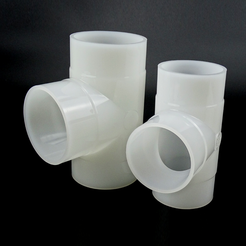
Deciding between equal tees and reducing tees forms the core of your layout strategy. An equal tee maintains the same diameter across all three ports. A reducing PVDF branch tee natively steps down the diameter at the intersecting port. Choosing a native reducing tee saves physical space. It eliminates the need for separate reducer fittings. Fewer fittings mean fewer weld joints. This reduction directly lowers the risk of future leaks. However, equal tees offer more flexibility if future expansion plans remain uncertain. You can always add a reducer later if needed.
You must also evaluate run flow versus branch flow dynamics. Extracting fluid into a branch alters the Reynolds number of the remaining fluid in the main header. The main line loses both volume and velocity. This sudden drop can transition the flow from turbulent to laminar. If your process requires continuous mixing downstream, laminar flow will ruin the chemical dispersion. You must calculate the resulting Reynolds number past every major junction. A properly sized branch flow fitting ensures both lines maintain their required flow regimes.
Material purity and compliance represent non-negotiable requirements. Your selected chemical piping tee must meet recognized global standards. ASTM D3222 and ISO 10931 dictate strict manufacturing tolerances. These standards guarantee chemical resistance against highly aggressive acids and bases. They also ensure structural integrity under dynamic flow stress. Non-compliant fittings may look identical but will deform under high temperatures. Always verify certification documents before authorizing procurement.
Small-bore branching presents unique fluid dynamic challenges. Pipes ranging from DN20 to DN50 handle smaller volumes but suffer from outsized friction effects. Viscosity plays a dominant role in these narrow passages. Thick fluids drag heavily against the pipe walls. Furthermore, installation methods impact small-bore performance heavily. Socket fusion often pushes molten polymer inward. This creates internal weld beads. These beads restrict the internal area drastically in small pipes. A 3mm bead in a DN25 pipe creates a massive flow obstruction. You must account for this restriction when calculating pressure drops.
Large-bore distribution headers span DN65 to DN110. These systems require comprehensive flow balancing strategies. Standardizing on a single DN20 DN110 tee framework simplifies the procurement process. It allows maintenance teams to stock a predictable matrix of spare parts. However, sizing large headers demands careful attention to pressure ratings. Standard Dimension Ratio (SDR) dictates the relationship between outside diameter and wall thickness. Wall thickness variations directly alter the true internal diameter (ID).
An SDR 11 pipe handles higher pressure than an SDR 21 pipe because it has thicker walls. Thicker walls mean a smaller internal diameter for the same nominal pipe size. If you assume the nominal size equals the true ID, your velocity calculations will be entirely wrong. A smaller ID pushes the fluid velocity higher. This forces a corresponding increase in friction loss. You must cross-reference manufacturer specification sheets to find the exact ID for your specific SDR rating.
Weld intrusions compromise sensitive flow-balancing applications. The turbulence generated by an internal bead distorts flow profiles before the fluid even enters the branch. Infrared (IR) butt welding offers a superior alternative to socket fusion. IR welding applies precise, non-contact heat. This technique produces incredibly smooth internal joints. It eliminates the protruding beads entirely. Engineers prefer IR welding for all critical chemical dosing networks. The initial equipment cost is higher, but the hydraulic benefits justify the investment.
Thermal expansion at junctions introduces severe mechanical risks. PVDF has a specific, well-documented coefficient of thermal expansion. Pipes lengthen as process temperatures rise. Tee branches act as rigid anchor points within the piping network. If you fail to manage this expansion, the pipe will push aggressively against the junction. Improper support spacing near the tee causes massive shear stress. This stress eventually cracks the fitting. You must design proper expansion loops. Install directional sliding supports to guide the movement away from the branches.
Cavitation destroys polymer fittings rapidly. High-velocity fluids experience a localized pressure drop as they navigate tight branches. If this localized pressure falls below the vapor pressure of the handled chemical, the liquid boils. Vapor bubbles form inside the fluid stream. As the fluid exits the restriction and pressure recovers, these bubbles collapse violently. This collapse blasts the inner wall of the fitting. Over time, cavitation erodes the PVDF material completely. You must identify high-velocity branch junctions during the design phase. Widen the branch diameter or reduce upstream pressure to keep local pressure safely above the vapor limit.
Selecting the right components requires strict verification of manufacturer data. Technical catalogs contain vital performance metrics. Look specifically for pressure and temperature derating curves. PVDF loses pressure-handling capacity as temperatures increase. You must verify the fitting can handle your maximum operating pressure at your maximum process temperature. Request exact K-factors for both straight and diverging flows. Check the dimensional tolerances. Tight manufacturing tolerances ensure better alignment during welding, which prevents internal flow disruption.
Modeling software compatibility matters immensely. Modern engineers rely on digital fluid modeling before procurement. Software platforms like Pipe Flow or FluidFlow predict system performance accurately. You must ensure your chosen sizing data translates correctly into these programs. Input the exact internal diameters and K-factors. Run the simulation to observe the pressure drops across every branch. This digital validation prevents catastrophic operational failures during commissioning.
Finally, evaluate the Total Cost of Installation (TCI). Do not just look at the raw unit price of the parts. Molded reducing tees carry a higher initial purchase price. However, they install much faster. Equal tees fabricated with secondary reducers cost less upfront. Yet, they double the required weld count. Extra welds require more expensive labor hours. They also increase the time spent on quality assurance and pressure testing. Weighing these installation factors often proves the molded reducing tee is the more economical choice.
Sizing a PVDF tee for balanced flow demands precision and foresight. You must align exact internal diameters with target fluid velocities. Relying on nominal pipe sizes leads to calculation errors and systemic inefficiencies. Accounting for diverging head loss guarantees your pumps can deliver the required volume to distant branches. Managing Reynolds numbers ensures fluid behaves predictably after every junction.
Take immediate action on your next design iteration. Calculate your required branch K-factors using accurate fluid modeling tools. Confirm your system's SDR requirements to determine true internal diameters. Consult manufacturer dimension charts to verify tolerances before making purchasing decisions. Finalize your bills of materials only after completing these crucial engineering checks. These proactive steps ensure your chemical piping system operates safely and efficiently for decades.
A: Pressure drop depends entirely on flow direction and velocity. Diverging flow into a branch typically carries a K-factor between 1.2 and 1.8. Straight-through flow usually features a lower K-factor between 0.3 and 0.5. You must calculate the exact head loss using your specific volumetric flow rate to size your pumps correctly.
A: Yes, but this approach introduces severe risks. Exceeding 2.5 m/s in chemical lines significantly increases the chance of water hammer. High speeds also accelerate wear on the polymer walls. It is much safer to control velocity using appropriate regulating valves rather than drastically restricting the physical pipe diameter.
A: Absolutely. A lower SDR number indicates a higher pressure rating, which requires thicker pipe walls. For any given nominal pipe size, thicker walls reduce the true internal diameter. This restricted flow area increases fluid velocity and elevates friction loss. You must base all balancing calculations on the true internal diameter.


