
close
Choose Your Site
Global
Social Media


Views: 0 Author: Site Editor Publish Time: 2026-07-22 Origin: Site


Specifying a valve for harsh chemicals presents a specific engineering challenge. You face even stricter hurdles in ultra-pure water applications. You need a solution where extreme corrosion resistance remains critical. Exact flow metering is equally vital for process stability. Engineers choose fluoropolymers for their exceptional chemical inertness. However, getting accurate PVDF needle valve sizing requires more than a simple pipe measurement. It is a strict mathematical requirement. You must ensure stable system performance at all times. Proper calculations prevent premature valve degradation. Failing to size correctly leads to catastrophic system fluctuations. Your chemical dosing loops will fail entirely. The internal tapered pin requires optimal flow dynamics to work. This guide provides the definitive engineering criteria you need. We help you specify the exact dimensions for your system. We determine the exact flow capacity required. You will learn step-by-step decision frameworks. We explore flow coefficient calculations deeply. We also cover critical thermal constraint evaluations. You can protect your entire fluid network effectively.
Cv is the core metric: Proper sizing relies on calculating the required Flow Coefficient (Cv) based on your system’s specific flow rate, pressure drop, and fluid specific gravity.
Oversizing is the primary failure mode: Selecting a valve based solely on pipe size rather than flow demand destroys resolution and leads to poor fine flow control.
P-T curves dictate feasibility: PVDF (Polyvinylidene fluoride) has strict pressure-temperature (P-T) derating curves that must be cross-referenced with your operating conditions before final selection.
Connection type impacts installation: Choosing between threaded, flanged, or true union connections depends on system pressure, scalability, and maintenance access.
Improper valve sizing introduces severe operational risks to your facility. You compromise system stability almost immediately. You also risk damaging expensive critical infrastructure. Sizing a precision flow valve requires exact engineering discipline. The tapered needle relies on specific fluid velocities. Many engineers fall into the oversizing trap repeatedly. They simply match the valve directly to the existing line size. This geometrical approach is heavily flawed. An oversized valve operates too close to its fully closed position. Fluid velocity spikes dramatically through a tiny opening. This high velocity creates erratic flow patterns. It also accelerates physical component wear through erosion. You lose the exact resolution needed for critical processes. A tiny handle adjustment causes a massive flow surge. Operators cannot fine-tune the system accurately.
Undersizing presents an equally dangerous risk profile. A valve chosen too small generates excessive pressure drops. You force too much volume through a restricted orifice. You might trigger dangerous choked flow conditions. System fluids can cavitate under these intense pressure drops. Cavitation bubbles form and collapse violently inside the body. Operators often hear this as gravel passing through the pipe. These micro-explosions damage the internal polymer structure permanently. They pit the plastic surfaces beyond repair.
A properly selected unit operates optimally between 20% and 80% open. We consider this the success criteria zone for engineering. It guarantees maximum adjustability for operators. Your system maintains stable metering under normal conditions. You avoid extreme stroke ranges entirely. Control remains predictable and highly responsive. You extend the operational lifespan of the equipment significantly.
The Flow Coefficient (Cv) defines your sizing baseline precisely. You cannot select equipment safely without it. It acts as the universal metric for fluid restriction. The standard Cv equation for liquids is straightforward. You calculate it as `Cv = Q * √(SG / ΔP)`.
Q represents your system flow rate in Gallons Per Minute (GPM). You must determine your normal operating flow first.
SG stands for Specific Gravity of your chosen fluid. Pure water serves as the 1.0 baseline.
ΔP denotes the allowable pressure drop across the valve in psi. This is the difference between upstream and downstream pressure.
Specific gravity plays a major role in your results. Dense chemicals behave very differently than plain water. Fluid density alters the Cv requirement significantly. Sulfuric acid and sodium hypochlorite demand careful calculation adjustments. You need a higher Cv to move heavier fluids. A 5 GPM flow of water requires a smaller orifice than a 5 GPM flow of concentrated acid.
Specific Gravity Comparisons for Common Industrial Fluids | ||
Fluid Classification | Common Industrial Chemical | Typical Specific Gravity (SG) at 68°F |
|---|---|---|
Baseline Reference | Ultra-Pure Water (UPW) | 1.00 |
Light Halogen Compound | Sodium Hypochlorite (12.5%) | 1.20 |
Heavy Caustic/Alkaline | Sodium Hydroxide (50%) | 1.53 |
Dense Acidic Solution | Sulfuric Acid (98%) | 1.84 |
Pressure drop assumptions require careful and deliberate thought. You must determine an acceptable ΔP for your network. Never assume a zero pressure drop under any circumstances. Zero pressure drop makes mathematical sizing physically impossible. A piping system always loses some pressure across the restrictive orifice. We generally recommend aiming for a 2 to 5 psi drop.
Once you calculate the required Cv, consult the manufacturer data. Review their published engineering data sheets carefully. Compare your calculated number against their specific published Cv curves. Find the orifice size offering your required Cv. Ensure it lands right within the ideal 20% to 80% stroke range. Do not guess or estimate these figures.
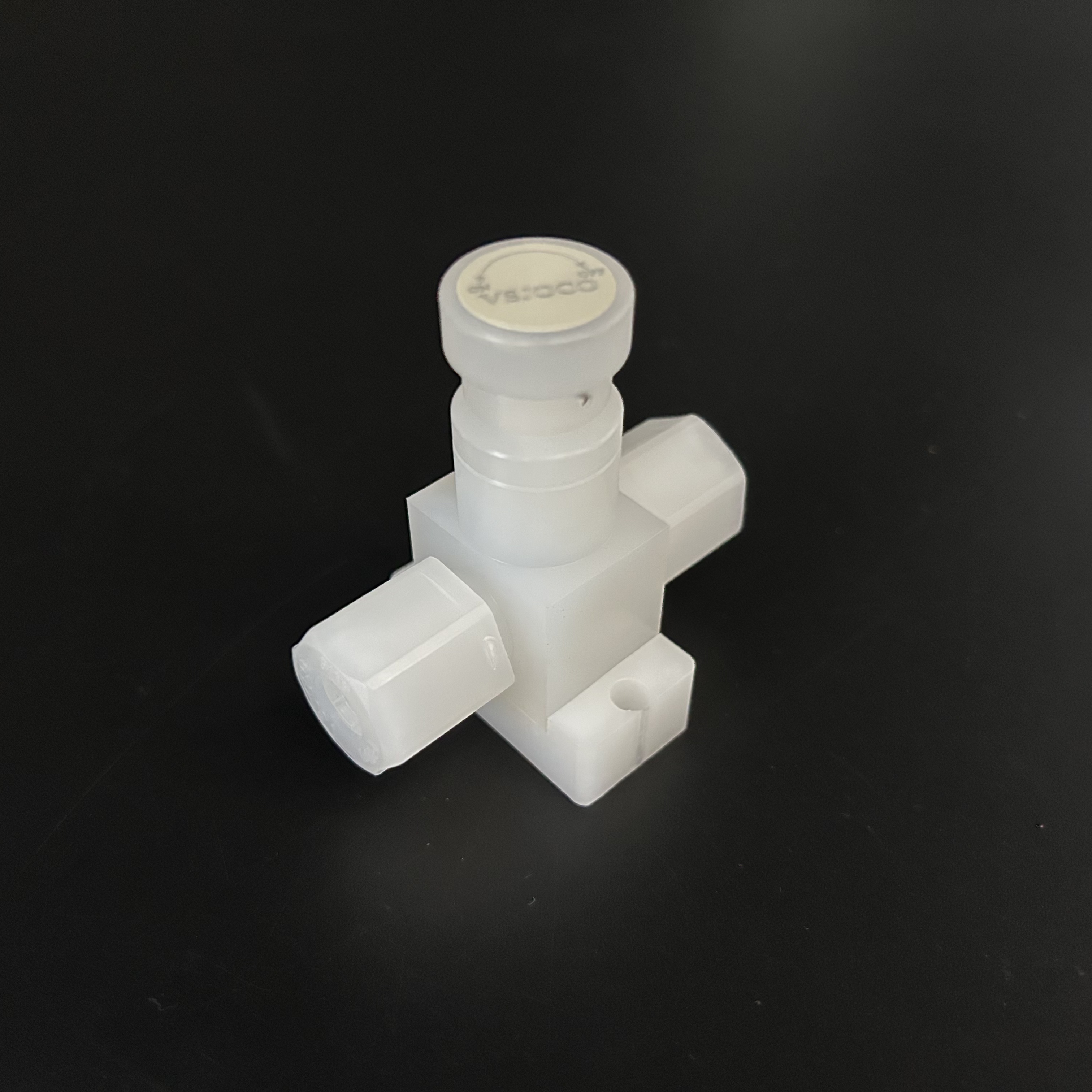
PVDF features strict thermal constraints that you must respect. You must monitor maximum operating temperature limits constantly. They typically max out around 240°F (115°C) in standard applications. However, temperature and pressure share an inverse relationship. Pressure ratings plummet rapidly as system temperatures rise. You cannot apply standard ambient pressure ratings to heated fluids. A valve rated for 150 psi at 70°F behaves differently when hot. It might only handle 50 psi at 180°F safely. Derating curves are rarely linear. They often drop steeply above 150°F. Always consult the specific derating chart before finalizing designs.
Chemical compatibility requires holistic verification from your engineering team. A PVDF regulating valve handles aggressive acids effortlessly. It resists severe halogens exceptionally well. But the tough polymer body is only half the equation. You must size and specify the internal O-rings carefully. Ensure the FKM/Viton, EPDM, or PTFE seals match your exact chemical makeup. A seal failure destroys system integrity instantly. Even if the plastic survives, melted O-rings cause catastrophic leaks. Chemicals can cause elastomers to swell or harden.
Consider fluid viscosity during your engineering evaluation phase. Standard Cv formulas assume you pump Newtonian fluids. Water serves as the behavioral model here. Highly viscous fluids resist flow aggressively through narrow passages. They require adjusted sizing calculations immediately. You must compensate for the extra internal friction. Thicker fluids demand specialized engineering correction factors. These factors guarantee sizing accuracy for syrup-like chemicals. Ignore viscosity, and your system will severely underperform.
Line size rarely dictates valve size directly in precision systems. You often need significantly smaller valves. A 1-inch pipe might strictly require a 1/2-inch unit. This sizing mismatch allows you to achieve the necessary Cv. This remains especially true for any precise chemical dosing valve application. We highly recommend using proper concentric pipe reducers. Never upsize the valve just to fit the pipe geometrically. It ruins flow resolution entirely.
Evaluating connection types ensures secure and lasting installations. You have three primary options available:
NPT/Threaded Connections: These remain highly cost-effective. They serve as the standard for smaller lines. However, they require chemically compatible thread sealants. You must avoid PTFE tapes that lubricate threads excessively. Over-lubrication leads to cracked plastic bodies during tightening. You create wedge-like stress on the female ports.
Flanged Connections: These prove ideal for larger industrial runs. They handle high-vibration areas easily. Flanges meet strict compliance environment standards. They distribute mechanical stress evenly across the joint. You must use a star-pattern tightening sequence here.
True Union Connections: These work best for intensive maintenance systems. They allow rapid cleaning and inspection. You can replace the central unit without cutting any pipe. The union nuts unscrew to release the main body instantly. O-ring face seals prevent leaks effectively.
Integration with existing infrastructure matters immensely. You must plan for dissimilar piping materials. Consider how to mate a PVDF unit to CPVC networks securely. You might also connect it to PTFE-lined steel pipes. Use appropriate transition fittings to prevent leaks. Proper transitions manage different thermal expansion rates safely. Plastics expand much faster than metals under heat.
Thermoplastics require careful mechanical planning during installation. PVDF is chemically strong but sensitive to physical bending stress. You must address system vibration risks immediately. The valve must be supported entirely independently. Do not rely on adjacent piping to hold its weight. Independent support brackets prevent dangerous thread cracking. They also eliminate hazardous flange stress entirely. Thermoplastics experience significant thermal expansion. You must design expansion loops into your piping framework.
Filtration requirements demand strict attention from your maintenance staff. Needle designs utilize very small internal orifices. Particulates cause immediate problems here. We strongly recommend installing upstream filtration. A simple 50-micron strainer prevents debris from clogging the narrow passage. It also stops hard abrasive particles. They will score the delicate plastic needle and seat otherwise. Scored seats cause continuous leaks even when fully closed.
Follow this strict shortlisting logic to select your final unit:
Confirm your calculated Cv aligns with the exact 20-80% open operating range.
Validate all system parameters strictly against the manufacturer’s specific P-T curve. Ensure you check the highest possible operating temperature.
Verify elastomeric seal compatibility carefully against your exact chemical mixture. Check for potential seal swelling issues.
Select the safest, most appropriate mechanical connection standard for your layout. Plan for future maintenance accessibility.
Following these clear steps guarantees highly reliable fine flow control. You eliminate engineering guesswork entirely. You protect your facility from unexpected downtime. Your fluid network operates precisely as designed.
Effective equipment sizing remains an exercise in strict data validation. You must master Cv calculations and specific gravity adjustments. You also need to apply accurate thermal derating constantly. Move your procurement and engineering teams away from arbitrary line-size matching. Implement strict demand-based mathematical calculations instead. Precision systems demand mathematical rigor.
Calculate your exact system flow demands before reviewing hardware catalogs.
Cross-reference chemical density and maximum temperatures carefully against derating charts.
Always select smaller restrictive valves over oversized ones if system pressure permits.
Incorporate independent mechanical brackets to protect sensitive thermoplastic bodies from strain.
Install adequate upstream filtration to protect the delicate tapered pin from abrasives.
Take concrete action now by gathering your precise flow rate data. Collect your maximum system pressure and peak temperature parameters. Consult manufacturer engineering data sheets immediately. Reach out to a qualified application engineer for final design verification. Proper planning now saves thousands in maintenance later.
A: Yes, but the sizing calculation changes. Gas sizing requires factoring in compressibility, absolute inlet pressure, and absolute temperature.
A: Generally, select the smaller valve if the pressure drop is acceptable, as it maintains better fine flow control resolution. If the pressure drop is too high, select the larger valve but verify it won't operate below 20% open.
A: Often caused by over-tightening or using incompatible thread sealants that lubricate the thermoplastic too much, leading to split female threads. Always follow manufacturer torque specifications.
A: Absolutely. The valve's maximum pressure rating (usually at ambient temperature) must exceed the highest possible system surge pressure (water hammer), not just the steady-state operating pressure.


