
close
Choose Your Site
Global
Social Media


Views: 0 Author: Site Editor Publish Time: 2026-07-31 Origin: Site


Industrial fluid systems demand highly precise pump sizing. They also require vigilant energy management to remain competitive. Uncalculated directional changes in piping routinely introduce severe flow restrictions. They force pumps to work harder and drive up daily power consumption. Worse, ignored friction points can lead to outright system underperformance over time. This challenge multiplies in demanding processing environments. Addressing the exact fluid dynamic impact of a 45-degree directional turn becomes vital. We see this especially when handling highly corrosive or ultra-pure media.
While 45-degree turns operate much more efficiently than 90-degree corners, engineering calculations are rarely simple. The inherent material properties of fluoropolymers change the math entirely. Furthermore, your chosen joining technique heavily dictates final flow efficiency. In this article, you will learn how geometry affects hydraulic resistance. We will explore specific calculation variables needed for accurate modeling. Finally, we will show you how proper installation preserves theoretical efficiency gains in the field.
A PVDF 45 degree elbow typically produces only 40–50% of the pressure drop compared to a standard 90° elbow of the same diameter.
The inherent smooth internal bore of PVDF minimizes friction loss compared to metal alternatives, though directional turbulence still occurs.
Fusion methods (butt vs. socket) dictate the true internal diameter and subsequent flow disruption.
Replacing multiple 90° bends with 45° elbows can downgrade required pump head pressure, yielding long-term operational cost savings.
Water or chemical flow resists changing paths. When moving liquid hits a bend, momentum pushes it outward toward the far wall. Flow separates at the inner radius. This boundary separation creates immediate localized turbulence. Swirling eddies form and consume kinetic energy. You lose pressure head immediately. However, modifying the angle changes the severity of this separation. A sweeping 45-degree path guides the fluid gently. It prevents the violent collisions seen in abrupt right-angle turns.
Engineers measure this directional resistance using a specific K-factor. Straight pipes use continuous friction factors based on linear length. Fittings use discrete K-factors to represent sudden geometric losses. A standard 45-degree turn usually carries a K-factor between 0.35 and 0.42. The exact number depends heavily on the standard dimension ratio (SDR). This represents a drastically lower penalty than a sharper turn, which often exceeds a 0.75 K-factor. Using a PVDF 45 degree elbow cuts the mathematical resistance nearly in half. It allows you to maintain higher velocities without stressing the pump impeller.
Material properties provide another distinct advantage. Metals corrode and pit over years of service. Pitting drastically increases internal surface roughness. Fluoropolymers offer an incredibly smooth internal bore from day one. They maintain this pristine surface even under aggressive chemical attack. This smoothness translates to a superior Hazen-Williams coefficient. It minimizes the baseline friction occurring along the pipe walls. You experience minimal energy loss before the geometric shape even becomes a factor. Selecting the right PVDF pipe bend fundamentally improves your starting hydraulic variables.
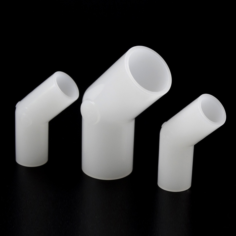
Theoretical knowledge requires practical application. You must calculate the exact pressure loss to size your pumps correctly. Several intersecting variables determine the final resistance value. Ignoring any single metric leads to flawed system curves.
We use a standard evaluation framework to model these losses accurately. You must define four core parameters before running your calculations:
Fluid Velocity: Faster flows create exponentially higher friction. Doubling the velocity quadruples the resistance. You must map the exact flow rate against the internal area.
Specific Gravity: Heavier acids require more kinetic energy to redirect. A liquid twice as dense as water impacts the fitting wall with twice the force.
Internal Diameter: Smaller pipes compound restriction effects. The boundary layer occupies a larger percentage of the total cross-sectional area.
Operating Temperature: Heat alters both fluid viscosity and density. These thermal shifts change the Reynolds number directly. Fluid dynamics shift drastically as temperatures rise.
Let us look at a data-driven comparison. We can contrast the theoretical resistance between different angles. This helps visualize the potential energy efficiency gains. The data assumes identical pipe diameters and flow velocities.
Hydraulic Resistance Comparison Chart
Fitting Type | Average K-Factor | Equivalent Length (L/D) | Relative Pressure Loss |
|---|---|---|---|
Standard 90° Elbow | 0.75 - 0.90 | 30 | 100% (Baseline) |
Standard 45° Elbow | 0.35 - 0.42 | 14 - 16 | 45% - 50% |
Long Radius 90° | 0.45 - 0.60 | 20 | 65% - 70% |
You must maintain transparent assumptions when reviewing these numbers. Standard calculations assume steady-state flow. They also assume a fully developed velocity profile entering the fitting. Reality often looks quite different. If you cluster multiple fittings closely together, they compound pressure losses unpredictably. The turbulence from one pressure drop elbow feeds directly into the next. You must leave adequate straight pipe runs between directional changes. This spacing allows the fluid stream to stabilize.
Engineering math provides a perfect baseline. However, implementation realities dictate true performance. The specific method you use to join fluoropolymer components directly impacts the actual resistance experienced in the field. Poor welding technique ruins brilliant hydraulic designs.
We must evaluate connection profiles carefully. Comparing a butt socket elbow against a standard infrared (IR) fusion fitting reveals stark differences. Socket fusion involves inserting the pipe into a wider fitting hub. This method carries specific internal risks. If the pipe does not seat fully, an internal gap remains. This void creates a small dead zone. High-velocity fluid shears across this gap, generating localized turbulence. Furthermore, misalignments create a sharp internal step. The fluid crashes against this step, sapping kinetic energy.
Butt fusion eliminates the overlapping hub entirely. Instead, it melts two flat pipe ends and presses them together. This method creates its own unique risks. Heating and pressing the plastic forces molten material inward and outward. This creates an internal weld bead. If an installer applies too much pressure, this bead grows excessively large. A massive internal bead acts as a secondary restriction orifice. It chokes the flow exactly where the fluid is already struggling to navigate the bend.
Industry best practices mitigate these welding risks. Professional installers follow strict DVS 2207-15 guidelines for fluoropolymer welding. These German standards dictate exact heating temperatures, soaking times, and joining pressures. Following these parameters controls internal bead size perfectly. It maintains the integrity of the internal bore. Careful adherence to standards validates your initial theoretical calculations. It guarantees the physical system matches your digital model.
System design always involves balancing competing priorities. Engineers must weigh footprint constraints against long-term energy efficiency. Industrial plant space comes at a premium. Running straight pipe is cheap, but navigating crowded facilities requires careful geometry.
We often face a battle between spatial and hydraulic efficiency. A 45-degree angle requires a much longer linear run to achieve the same directional offset as a sharp 90-degree corner. It eats up more horizontal or vertical space. You must assess when this footprint trade-off makes sense. In tight skid-mounted systems, you might have no choice but to use sharp corners. However, in main distribution headers, the physical space usually exists. Spreading the directional change over a longer physical distance yields massive hydraulic gains. It drastically reduces the motor power needed to move the fluid.
Handling aggressive media changes the decision matrix entirely. Pumping 98% sulfuric acid is vastly different from pumping municipal water. High-density acids carry massive momentum. When they slam into a sharp corner, they exert immense physical force on the outer wall. In a chemical pipeline bend, reducing turbulence minimizes localized wear. It also mitigates dangerous cavitation risks. Cavitation occurs when localized pressure drops below the fluid vapor pressure. Micro-bubbles form and violently collapse against the pipe wall. This phenomenon physically pits the plastic. Using gentler angles in halogen or acid systems prevents these sudden pressure drops. It protects the physical integrity of the piping network.
Procurement and engineering teams need clear criteria before making purchasing decisions. Selecting the right components ensures system longevity. You cannot afford to guess when handling dangerous chemicals under high pressure.
We recommend using a rigorous specification checklist. Verify the following parameters before authorizing any purchase:
SDR/PN Rating Matching: Ensure the fitting dimension ratio perfectly matches the straight pipe. Mismatches create internal steps that disrupt flow.
Certified Resin Grades: Confirm the manufacturer uses virgin, unpigmented fluoropolymer resins to guarantee chemical resistance.
Dimensional Standards: Verify whether your system utilizes ISO/DIN metric measurements or ASTM imperial sizing. Mixing standards guarantees catastrophic joint failure.
Weldability Documentation: Request documentation proving the fitting complies with DVS welding parameters for automated fusion machines.
You must also perform a thorough cost-to-outcome analysis. Designing with gentler offsets introduces slightly higher component complexity. You might need extra straight pipe lengths to make the geometry work. However, you must weigh this minor upfront effort against long-term operational savings. A highly optimized system requires smaller pumps. It consumes significantly less electricity every hour of operation. Furthermore, reducing physical stress on the pipe walls extends the system lifecycle dramatically. You spend less time performing maintenance and replacing worn components.
Your next steps involve gathering precise data for your specific application. Prompt your engineering team to consult the actual system curve data. Request specific 3D CAD models from the manufacturer to verify spatial fit. Always demand access to the manufacturer's certified K-factor charts. Relying on generic textbook numbers leads to sizing errors. Exact hydraulic modeling requires exact component data.
Replacing abrupt piping corners with 45-degree angles stands as a highly strategic engineering choice. This geometry fundamentally optimizes flow profiles within critical chemical networks. It drastically reduces pressure head requirements, allowing you to downsize pumps and conserve electrical energy. Fluoropolymer materials compound this advantage by offering virtually frictionless internal surfaces.
Realizing these theoretical efficiency gains relies entirely on execution. You must prioritize precision installation and adhere to strict welding protocols. Accurate, dimension-specific hydraulic calculations are mandatory. By combining smart geometry, premium materials, and flawless installation, your fluid handling system will deliver decades of safe, optimized performance.
A: A 45-degree fitting does not inherently "reduce flow" on its own. Instead, it offers significantly less hydraulic resistance. It produces roughly half the equivalent length of a standard 90-degree turn. This lower resistance allows the exact same pump to either deliver a higher volume of fluid or achieve the same flow rate while consuming less electrical energy.
A: Engineering rules of thumb typically assign an equivalent length (L/D ratio) of 14 to 16 for these turns. However, this number is not absolute. It varies strictly depending on the specific Standard Dimension Ratio (SDR) and the actual internal pipe diameter used in your facility.
A: Yes. While premium fluoropolymers safely handle continuous operating temperatures up to 140°C (284°F), thermal changes alter the fluid itself. Rising temperatures change both the viscosity and density of the media. This alters the Reynolds number and completely shifts the pressure drop outcome, even though the fitting geometry remains totally static.


