
close
Choose Your Site
Global
Social Media


Views: 0 Author: Site Editor Publish Time: 2026-07-30 Origin: Site


System failures in aggressive chemical handling carry incredibly high stakes. Relying on a single valve mechanism can easily lead to severe cross-contamination, catastrophic equipment damage, or serious safety hazards. Facility engineers often turn to polytetrafluoroethylene (PTFE) for its unmatched chemical resistance. However, technical realities quickly complicate this choice. PTFE possesses unique mechanical properties, specifically extreme rigidity and a high susceptibility to cold flow. These traits can completely compromise seating under specific system dynamics.
We wrote this article to provide a clear diagnostic framework for identifying why your fluid control components failed. You will learn how mechanical forces interact against rigid seals. Furthermore, we will show you how to specify the exact replacement or system upgrade necessary for robust, long-term fluid control. Let us explore the mechanics behind these critical failures.
PTFE’s lack of elastomeric "memory" makes it highly sensitive to particulate interference and low back-pressure environments, often leading to slow leaks rather than catastrophic mechanical breaks.
A standard non-return valve is not a compliant substitute for a certified backflow preventer in systems requiring absolute isolation of hazardous fluids.
Selecting the right replacement requires evaluating cracking pressure, system back pressure, operating temperatures, and seating mechanisms rather than just chemical compatibility.
Upstream filtration and strict adherence to installation orientation are critical to preventing premature valve failure.
Process contamination directly impacts production viability. Aggressive media reversing into upstream lines ruins entire product batches. Yield loss severely damages facility budgets and operational timelines. When a highly reactive acid bypasses a seal and enters a water purification line, the resulting chemical reaction can destroy expensive upstream filters. These events halt manufacturing entirely.
Safety and compliance realities present another major challenge. Regulatory agencies draw a strict line between basic flow control and mandated isolation. Handling hazardous liquids requires absolute certainty. A simple flapper cannot protect municipal water supplies or worker safety zones from toxic exposure. Robust chemical backflow prevention requires verified isolation mechanisms. Regulatory codes frequently mandate redundant sealing and atmospheric venting.
You must clearly define success criteria for a permanent fix. A successful intervention guarantees verifiable zero-leakage sealing. It ensures strict dimensional stability across your entire operating temperature range. Finally, it establishes predictable maintenance intervals. Engineers cannot simply replace a broken component with an identical unit. You must upgrade the system to handle the specific mechanical forces causing the failure.
Best Practice: Always map system fluid dynamics and pressure variables before specifying your sealing materials.
Common Mistake: Relying exclusively on chemical compatibility charts while entirely ignoring mechanical flow requirements.
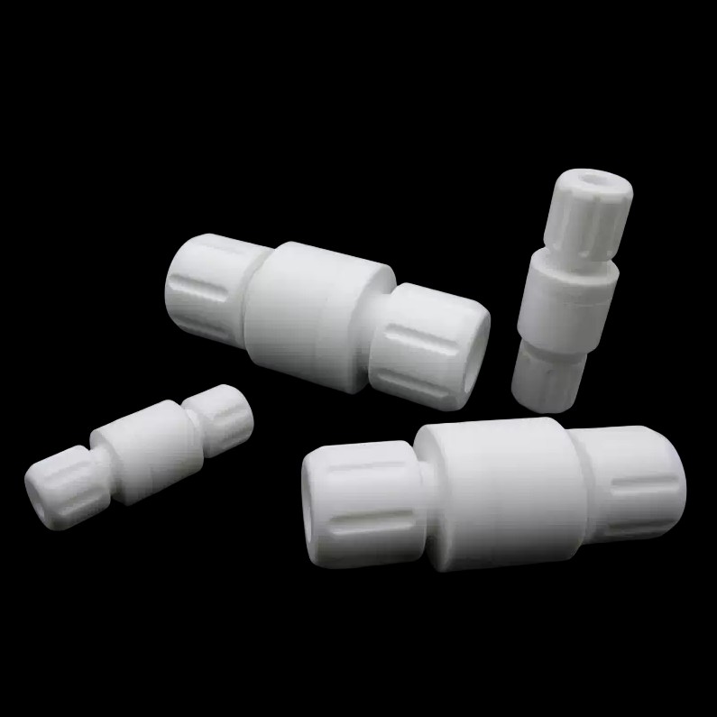
Many system designs rely on reverse fluid pressure to force the internal poppet or diaphragm against the seat. A standard PTFE check valve requires substantial force to create a tight seal. Unlike soft rubber, rigid plastics do not naturally conform to microscopic surface imperfections.
Gravity alone rarely creates a vapor-tight seal against rigid PTFE. Low-pressure differentials fail to generate the necessary mechanical energy. Soft elastomer seals might achieve zero-leakage at 0.5 psi of back pressure. In contrast, rigid polymer seats often require 5 to 10 psi of sustained reverse pressure to close completely. Without this force, the valve weeps fluid continuously.
The inherent hardness of PTFE prevents it from sealing around debris. Softer elastomers like EPDM or FKM simply deform around a small particle. They swallow the debris and maintain the seal. PTFE cannot perform this action. It stops rigidly against the particle.
Even microscopic crystallization from chemical media can hold the valve open. Process fluids often precipitate salts or form tiny crystals when temperatures drop. These microscopic particles lodge between the poppet and the seat. This creates a continuous bypass. Fluid steadily leaks backward through the tiny gap, rendering the component useless for absolute isolation.
PTFE frequently deforms under continuous mechanical stress. Engineers call this phenomenon cold flow or creep. Internal springs constantly push the poppet into the seat. Over several months, this steady load permanently alters the material shape. High-temperature fluctuations aggressively accelerate this deformation.
Thermal cycling alters the precision-machined tolerances of a rigid system. When heated, the material expands. When cooled, it contracts. After dozens of thermal cycles, a precision PTFE one-way valve loses its original seating alignment. The poppet no longer matches the seat geometry perfectly. This dimensional instability guarantees an eventual slow leak.
Flow turbulence rapidly destroys internal valve components. Installing a valve too close to a pump discharge or a sharp elbow subjects it to violent fluid velocity profiles. The internal poppet chatters rapidly. This constant hammering physically destroys the machined sealing surfaces.
Installation orientation profoundly impacts performance. Many designs depend heavily on gravity to assist the closing mechanism. Installing a gravity-dependent corrosive fluid valve in a horizontal line negates its mechanical closing force. Even incorrect vertical orientations will completely neutralize the internal spring dynamics. You must strictly follow the manufacturer flow direction arrows and orientation guidelines.
We must strongly differentiate a basic non-return valve from a dedicated backflow assembly. Basic valves simply keep pipes primed. They provide unidirectional flow to prevent pumps from running dry. They rely on a single sealing surface. They offer no redundancy.
A dedicated backflow preventer offers a highly engineered safety mechanism. These systems provide absolute isolation. They feature double redundant checks. They include atmospheric vents to dump fluid if the primary seal fails. They incorporate integrated test cocks for routine performance verification. They handle extreme toxic exposure risks reliably.
You need a framework for evaluating system requirements. A standard valve suffices for benign fluids where minor leakage causes no harm. However, a facility must upgrade to a highly engineered prevention system to meet safety compliance codes when handling hazardous media. You must protect potable water supplies and human operators.
Avoid dangerous false equivalencies. Engineers frequently fall into the trap of assuming a basic check mechanism provides absolute shut-off. This assumption leads to catastrophic failures in critical isolation scenarios. A single rigid seat can never guarantee zero-leakage under all dynamic conditions.
Specifying a replacement requires matching the internal cracking pressure directly to your system dynamics. The internal spring mechanism must align perfectly with your pump output and the static head pressure. If the spring is too strong, the valve restricts forward flow. If the spring is too weak, it fails to close against minor reverse currents.
Consider advanced material enhancements. Standard virgin PTFE suffers from severe cold flow. Modified PTFE provides vastly superior dimensional stability. It resists creep under continuous load. Alternatively, you can encapsulate a softer elastomer core inside a PTFE shell. This hybrid approach gives you extreme chemical resistance combined with a tight, compliant seal.
You must carefully compare different design architectures based on fluid viscosity and particulate load. Spring-loaded poppet valves work well for clean fluids. Swing checks handle higher particulate loads but require specific orientations. Diaphragm checks offer excellent sealing at low pressures but struggle with highly viscous slurries.
Valve Architecture | Best Fluid Match | Particulate Tolerance | Minimum Seating Force |
|---|---|---|---|
Spring-Loaded Poppet | Clean, low-viscosity chemicals | Low | Medium to High |
Swing Check Design | Medium viscosity, basic wastewater | Moderate | Low (Gravity Dependent) |
Diaphragm Design | Ultra-pure liquids, high cycling | Very Low | Very Low |
Use a strict step-by-step shortlisting logic for procurement:
Define the system static head pressure: Measure the exact reverse force available to close the seat.
Analyze the fluid thermal profile: Document temperature spikes that cause dimensional changes.
Specify the internal mechanism: Choose poppet, swing, or diaphragm based on your specific particulate load.
Select material enhancements: Choose modified polymers or encapsulated elastomers to overcome cold flow.
Calculate lifecycle risks: Balance procurement costs against potential downtime and safety hazards.
Upstream protection guarantees long-term reliability. You must install high-quality strainers or filters ahead of the rigid seat. Hard particulates easily score and scratch machined polymer surfaces. A scratched seat leaks permanently. Filtering the media preserves the smooth sealing geometry.
Follow strict installation best practices regarding pipe runs. You need sufficient straight pipe lengths before and after the component. Industry standards recommend at least five to ten pipe diameters of straight run upstream. This ensures laminar flow. Laminar flow prevents the internal poppet from vibrating and chattering against the seat.
Establish rigorous inline testing protocols. Do not wait for a catastrophic failure. Install pressure gauges immediately upstream and downstream. Monitor the differential pressure regularly. Set a routine testing schedule to detect slow reverse-flow leaks early. Routine monitoring turns unpredictable emergencies into planned maintenance events.
Diagnosing a failing fluid control component requires looking far beyond simple chemical compatibility. You must deeply understand the mechanical system forces interacting with the sealing surfaces. Rigid polymers offer incredible chemical defense, but they demand precise flow conditions to function safely.
We strongly recommend conducting a full system audit before procuring any replacement parts. Measure your actual flow rates. Document your precise pressure drops. Analyze the purity and particulate load of your media. Understanding these variables prevents repeat failures.
Do not guess when handling aggressive chemicals. Consult directly with a fluid control engineering specialist. They will help you specify the exact architecture and material enhancements required for your unique application.
A: Yes, excessive back pressure can permanently deform the PTFE seat or damage internal springs if the valve is not rated for those limits. Constant extreme pressure pushes the material beyond its yield strength, causing permanent cold flow and destroying the precision seal.
A: Inspection frequency varies by media aggressiveness and cycle rate. However, critical process lines require bi-annual or annual testing. Industry standard reliability practices mandate regular visual checks and pressure differential monitoring to catch slow leaks early.
A: Chattering typically points to an oversized valve for your current flow rate. It also occurs if you place it too close to a turbulent source like a pump discharge. This turbulence causes rapid open and close cycling that quickly destroys the internal seat.


